 English
  русский
 عربى
عربى Español
Camshaft Phase Regulators are systems that enable an engine controller to govern camshaft timing in actual time, including for emissions or performance requirements. The actuator is pushed by way of an AC voltage signal from the onboard engine controller and makes use of a sensor to pick out each cylinder camshaft's function through a rotating disc. The sensor is activated by using an AC sign from the onboard engine controller that stimulates an exciter coil within the camshaft phaser with up to two,500 cycles consistent with 2nd frequency. The sensor is attached to an exciter coil through mutual inductance and generates an electromagnetic area within its camshaft phaser which, when turned on, rotates a slot in the sensor at up to 0.5 Hz frequency, generating an AC voltage sign which suggests wherein the first-cylinder camshaft sits; this output sign is transmitted lower back to an onboard engine controller for interpretation.
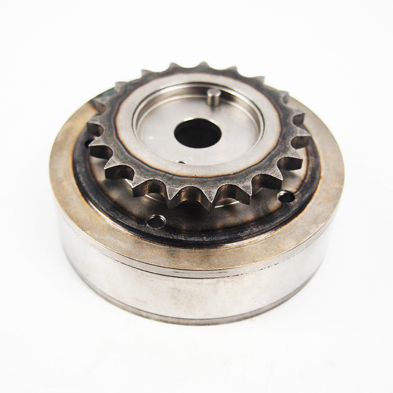
FIG. 2 provides an axial cutaway view of a camshaft phaser. A rotor 18 is suspended inside its housing with one-manner valve 12 and locking pin meeting 26 connected thereto, featuring a nostril element 62 that extends in locking mode to engage pin bore 29 of returned plate 22 for mechanical coupling/decoupling of both the rotor and stator rotors.
Camshaft segment adjusters include a 2d oil hole, a movable valve plate with two groove facet surfaces related to the primary oil hollow, and an on/off one-way valve switchable between blocked and unblocked states. When extended, this plate suits into either of two groove backside surfaces on its stop surface - either of which connects back to its respective oil hole.
FIGS. Three and four display a simulation model of managing overall performance, pace profile, and electricity intake for camshaft cause wheels with three, 4, or 6 teeth in addition to sensor fusion tactics that utilize resolver indicators for 3, 4, or 6-teeth camshaft cause wheels as well as for sensor fusion strategies that utilize resolver indicators as sensor statistics. Simulation results found that sensor fusion strategies decreased phasing duration associated with target bandwidth of /2degCA via as much as 204 milliseconds while in comparison with three-toothed trigger wheels even as overshooting became saved inside its goal bandwidth range for all simulation consequences.
Simulation outcomes also reveal that growing the variety of trigger teeth greatly shortens the phasing period at the same time as maintaining nearly the same overshoot and power intake stages. Sensor fusion methods substantially increase manipulation accuracy and reliability for synchronization approaches. Implementing the synchronization undertaking immediately inside either an engine control unit or camshaft phaser may additionally enable one to cast off an electric motor resolver; however, this calls for each sensor and resolver to be placed inside one ECU/EMC, otherwise, verbal exchange delays between these devices can reason extreme difficulties.
 View More >>
 View More >>
 View More >>
 View More >>
 View More >>
 View More >>
 View More >>
 View More >>
 View More >>
 View More >>
 View More >>
 View More >>


