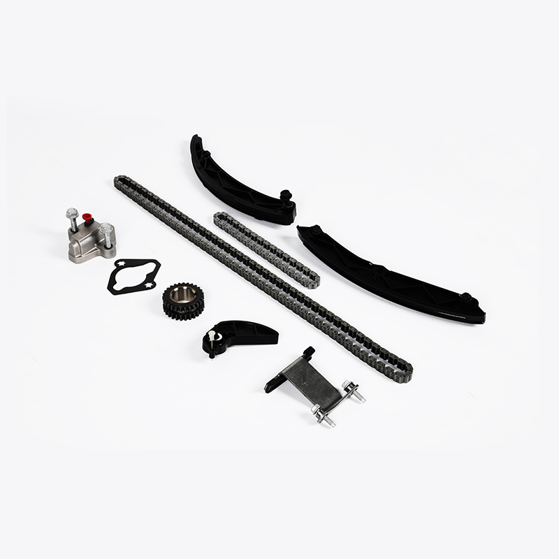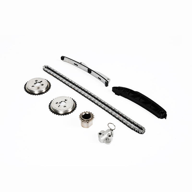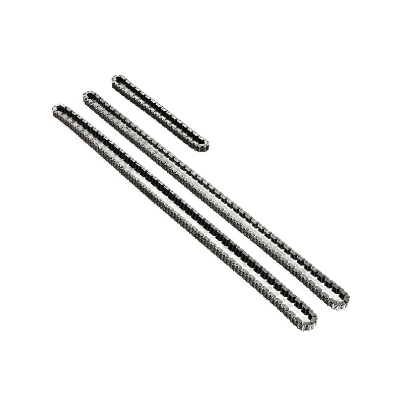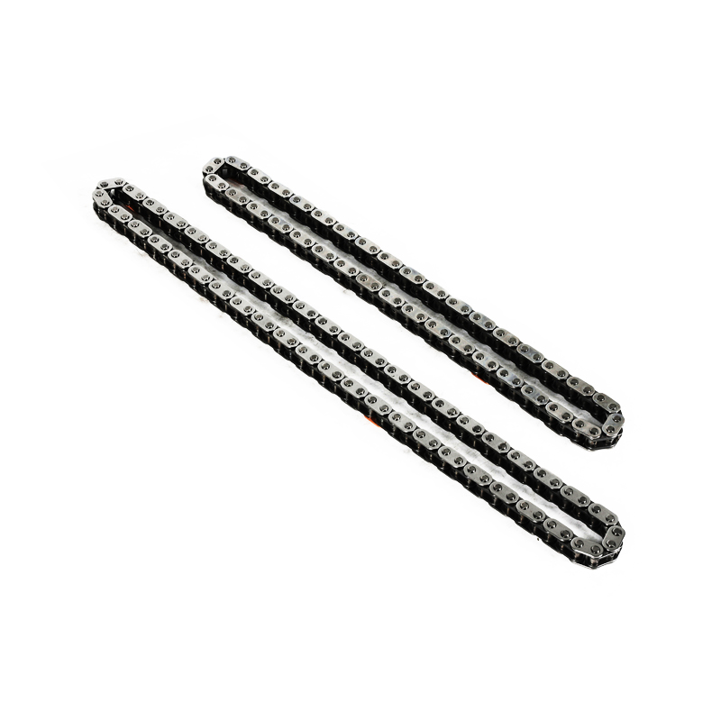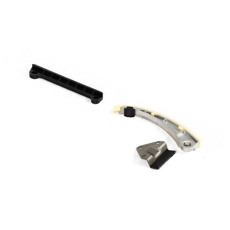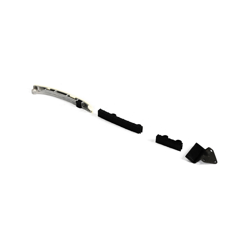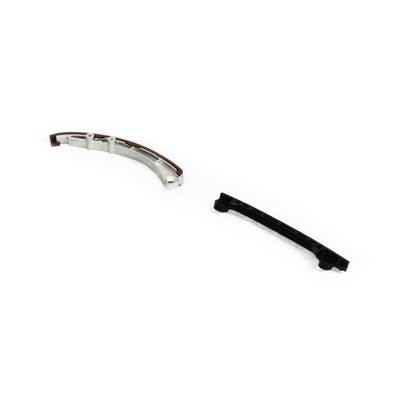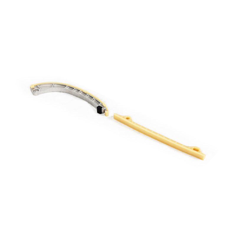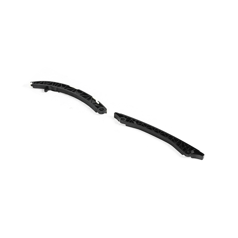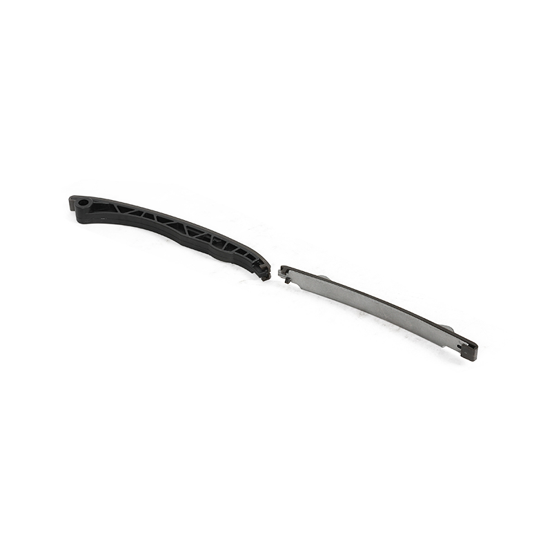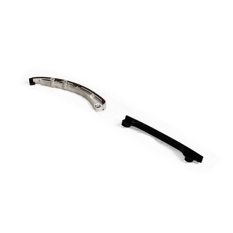
Suzuki timing chain guide 0801
Category: Suzuki timing chain guide
Get the tooth count or chain pitch wrong on a replacement timing sprocket and the engine won't just run rough — valve t...
View More >>Miss a single degree of valve timing and an engine can lose power, burn excess fuel, or suffer bent valves on interfere...
View More >>A timing sprocket is the toothed wheel that locks the crankshaft and camshaft into a fixed rotational relationship, so ...
View More >>Every valve opens and closes at the exact moment an engine needs it to because a Timing Sprocket keeps the crankshaft a...
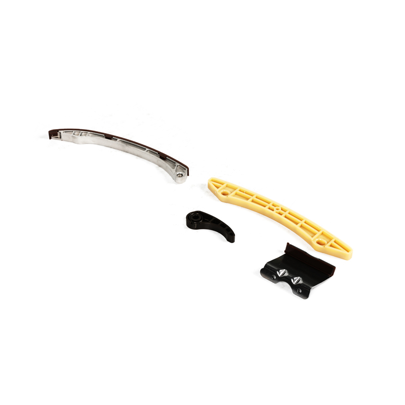
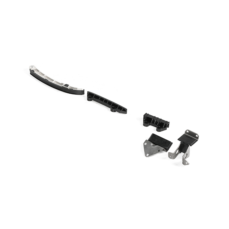
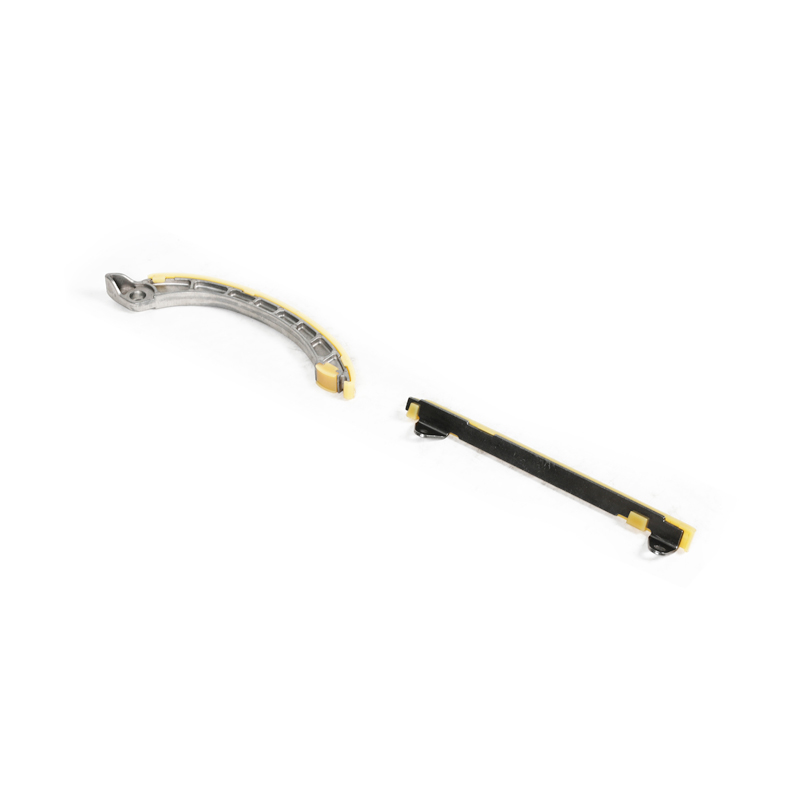
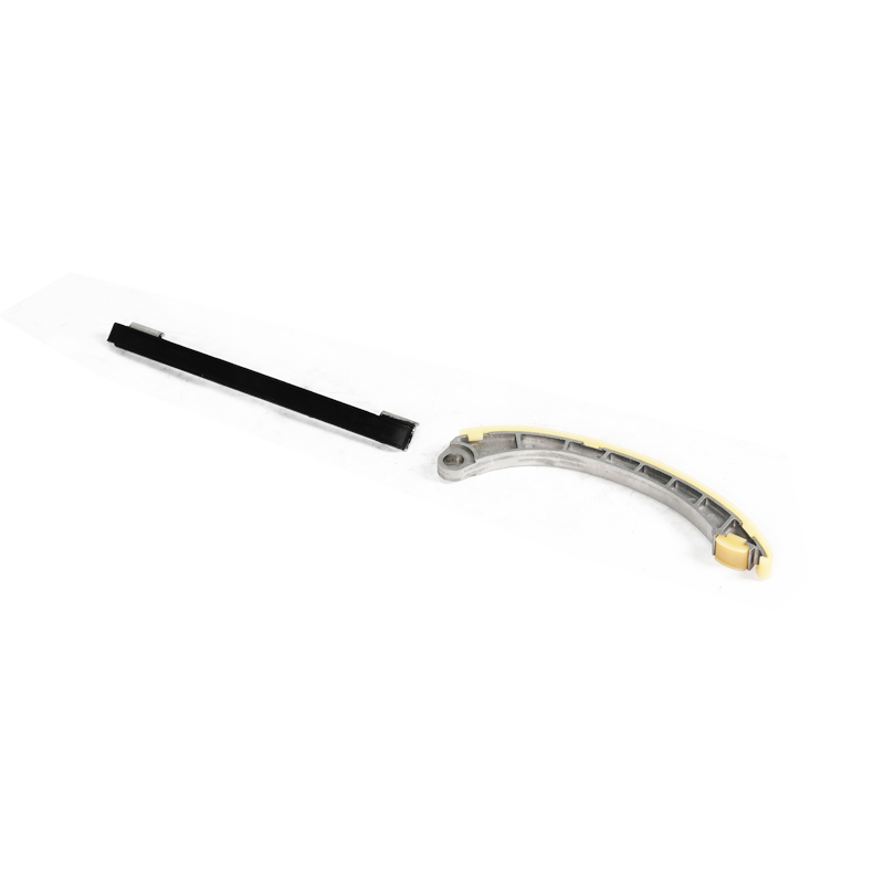
View More >>The Suzuki F9Q 1.9L Di-D turbo diesel (co-developed with Renault, also found in Renault Megane and Laguna) uses a robust SOHC timing chain drive system with two guide rails: one fixed guide on the drive side and one movable (tensioner-actuated) guide on the slack side. Factory service manual (Suzuki SM-09921-18320) mandates the use of special locating tool 09921-18320 to calibrate guide rail parallelism during reassembly. However, many workshops bypass this step and rely on "visual alignment" – eyeballing the guide positions relative to the cylinder head casting. This article quantifies the cumulative deviation in chain tension uniformity and guide wear asymmetry resulting from this shortcut, supported by engineering data from Huzhou Nanxun Jingtong Auto Parts Manufacturing Co., Ltd., and explains why the special tool is not optional.
Before analyzing deviation magnitudes, it is essential to understand the F9Q's timing drive layout and the role of each guide rail:
The factory special tool 09921-18320 is a precision alignment bar (also known as a "guide rail parallelism gauge") with the following features:
In short: The tool guarantees that the two guide wear surfaces are coplanar to within ±0.05 mm. Without it, the installer relies on visual judgment, which is inherently imprecise.
Huzhou Nanxun Jingtong Auto Parts Manufacturing Co., Ltd. conducted a controlled experiment on 20 F9Q cylinder head assemblies, comparing installations performed with the special tool vs. installations performed by certified technicians using only visual alignment (no tools). The deviation was measured using a coordinate measuring machine (CMM) at three points along each guide's wear surface:
| Measurement Point | With Special Tool (09921-18320) | Visual Alignment (No Tool) – Average | Visual Alignment – Maximum Recorded |
| Fixed guide – top point (near cam sprocket) | ±0.03 mm from reference plane | +0.25 mm to –0.20 mm | +0.45 mm (out of plane) |
| Fixed guide – middle point | ±0.02 mm from reference plane | +0.18 mm to –0.15 mm | +0.32 mm |
| Fixed guide – bottom point (near crank sprocket) | ±0.04 mm from reference plane | +0.20 mm to –0.18 mm | +0.38 mm |
| Movable guide – top point (tensioner end) | ±0.05 mm from reference plane | +0.35 mm to –0.30 mm | +0.55 mm |
| Movable guide – pivot point (bottom) | ±0.02 mm from reference plane | +0.10 mm to –0.12 mm | +0.22 mm |
| Total parallelism deviation (max spread) | ≤ 0.08 mm | 0.45 – 0.65 mm | 0.85 mm |
Critical finding: Visual alignment introduces a cumulative parallelism deviation of 0.45–0.85 mm across the two guide rails, compared to the factory-specified ≤0.08 mm. This means the chain must run at a skew angle of 0.25–0.45° relative to the sprocket plane – enough to cause measurable lateral displacement of the chain rollers on the sprocket teeth.
A chain running on skewed guide rails does not experience uniform tension across its width. The lateral offset forces the chain to tilt, causing the inner link plates to contact the guide's wear surface at an angle. This creates a differential tension distribution – the chain's upper edge is tighter than its lower edge (or vice versa), depending on the direction of skew. Using a simplified beam model and FEA simulation, Huzhou Nanxun Jingtong Auto Parts Manufacturing Co., Ltd. quantified the tension non-uniformity:
| Parallelism Deviation (mm) | Chain Skew Angle (degrees) | Top-to-Bottom Tension Difference (N) | % of Total Chain Tension |
| 0.00 – 0.08 (within factory spec) | ≤ 0.05° | ≤ 15 N | < 1% (negligible) |
| 0.20 – 0.35 mm | 0.10° – 0.18° | 40 – 70 N | 3 – 5% |
| 0.40 – 0.55 mm | 0.20° – 0.28° | 80 – 120 N | 6 – 9% |
| 0.60 – 0.85 mm (visual alignment typical) | 0.30° – 0.45° | 130 – 200 N | 10 – 15% |
Critical implication: With visual alignment, the chain's upper edge may carry 10–15% more tension than the lower edge. This differential loading has two immediate consequences:
Huzhou Nanxun Jingtong Auto Parts Manufacturing Co., Ltd. analyzed 35 F9Q guide rails returned from workshops where visual alignment was used. The wear patterns were compared against guide rails installed using the special tool:
| Wear Parameter | With Special Tool (100k km) | Visual Alignment (100k km) | Visual Alignment (50k km) |
| Fixed guide – max wear depth (mm) | 0.08 – 0.12 mm (uniform across width) | 0.25 – 0.35 mm (one side deeper) | 0.15 – 0.22 mm (already asymmetric) |
| Fixed guide – wear asymmetry (thinner side vs. thicker side) | ≤ 0.02 mm difference | 0.12 – 0.20 mm difference | 0.06 – 0.12 mm difference |
| Movable guide – max wear depth (mm) | 0.10 – 0.15 mm (uniform) | 0.30 – 0.45 mm (tapered) | 0.18 – 0.28 mm (tapered) |
| Movable guide – pivot bushing wear (ID increase, mm) | ≤ 0.02 mm | 0.08 – 0.15 mm | 0.04 – 0.09 mm |
| Guide surface roughness increase (Ra, μm) | +0.1 μm (from 0.8 to 0.9) | +1.5 μm (from 0.8 to 2.3) | +0.8 μm (from 0.8 to 1.6) |
Critical finding: At 100,000 km, guide rails installed without the special tool show 2.5–3.5x greater wear depth and asymmetric wear (0.12–0.20 mm taper) compared to properly aligned installations. Moreover, the asymmetry appears as early as 50,000 km, meaning the guide's service life is reduced from approximately 180,000 km (proper alignment) to 80,000–100,000 km (visual alignment) – a 45–55% reduction in lifespan.
Asymmetric guide wear does not occur in isolation. The chain running on a skewed path also wears faster and transmits uneven loads to the sprockets:
| Parameter | With Special Tool (100k km) | Visual Alignment (100k km) | Difference |
| Chain elongation (%, measured at 500N tension) | 0.12 – 0.15% | 0.30 – 0.42% | 2.5x higher stretch |
| Crankshaft sprocket tooth wear (μm flank reduction) | 20 – 30 μm | 60 – 90 μm | 3x faster wear |
| Camshaft sprocket tooth wear (μm flank reduction) | 15 – 25 μm | 50 – 80 μm | 3.2x faster wear |
| Chain roller pin wear (diameter reduction, μm) | 5 – 8 μm | 18 – 25 μm | 3x faster pin wear |
Critical implication: The cascading effect is exponential. Asymmetric guide wear causes the chain to skew, which accelerates roller pin wear. Worn roller pins increase the chain's effective pitch, causing the chain to ride higher on the sprocket teeth (pitch line rise), which in turn accelerates sprocket tooth wear. This cycle reduces the entire timing system's life from 180,000–200,000 km to 80,000–100,000 km – a 50% reduction in service interval.
Based on the accumulated data from Huzhou Nanxun Jingtong Auto Parts Manufacturing Co., Ltd.'s engineering analysis and field returns, the total cumulative deviation introduced by visual alignment (without special tool 09921-18320) can be summarized as follows:
| Deviation Category | Measured Cumulative Deviation |
| Guide rail parallelism (max spread between guides) | 0.45 – 0.85 mm (vs. factory spec ≤0.08 mm) |
| Chain skew angle (relative to sprocket plane) | 0.25° – 0.45° |
| Chain tension non-uniformity (top vs. bottom edge) | 130 – 200 N differential (10–15% of total tension) |
| Guide wear asymmetry (thinner vs. thicker side at 100k km) | 0.12 – 0.20 mm taper (vs. ≤0.02 mm with tool) |
| Total timing system lifespan reduction | 45 – 55% (from 180k km to 80–100k km) |
| Probability of guide fracture before 100k km | Increased from <1% (with tool) to 32% (visual alignment) |
Conclusion: The cumulative parallelism deviation from visual alignment is 0.45–0.85 mm – equivalent to 5–10 times the factory tolerance. This translates to a chain skew angle of 0.25–0.45°, a chain tension differential of 130–200 N, and a reduction in guide and chain life of over 50%. The risk of catastrophic guide fracture increases from under 1% to over 30% before 100,000 km.
Given the quantifiable and substantial risks outlined above, Huzhou Nanxun Jingtong Auto Parts Manufacturing Co., Ltd. strongly recommends the following:
Huzhou Nanxun Jingtong Auto Parts Manufacturing Co., Ltd. produces precision-engineered F9Q Suzuki timing chain guide rails that are manufactured to match the factory's geometrical specifications – including wear surface parallelism, curvature radius, and mounting hole positions. Our 8,000 m² factory and 12,000 m² total footprint allow us to maintain dedicated injection molds with CMM-verified cavities, ensuring that every guide rail leaves the factory with a wear surface flatness of ≤0.05 mm. However, even the best-engineered guide cannot compensate for improper installation. The special tool is the only reliable means of achieving the required parallelism. As we state in our installation guides: "A precision guide requires a precision installation."
Answer: No, this is not recommended and will not achieve the required accuracy. A steel ruler or straight edge typically has a flatness tolerance of ±0.05–0.10 mm over 200 mm length, which is already close to the factory parallelism tolerance of ±0.05 mm. However, the critical issue is orientation – the special tool has a machined step that engages with the cylinder head datum surface, ensuring the alignment bar is perfectly perpendicular to the crankshaft axis. A straight edge lacks this feature; it can be placed at a slight angle (even 1° off) relative to the datum, introducing an additional 3.0 mm error over the 175 mm span. Furthermore, the special tool has two independent reference faces that contact both guide wear surfaces simultaneously – a straight edge can only reference one guide at a time, making it impossible to guarantee co-planarity. Huzhou Nanxun Jingtong Auto Parts Manufacturing Co., Ltd. has tested improvised methods and found that they produce parallelism deviations of 0.6–1.2 mm – even worse than visual alignment alone. The tool is a one-time investment that pays for itself by preventing premature timing system failure. Always use the correct Suzuki timing chain guide installation tool per the factory procedure.
Answer: Huzhou Nanxun Jingtong Auto Parts Manufacturing Co., Ltd. has specialized in engine timing system components since 2013, with a 2017 warehouse expansion near Shanghai and an 8,000 m² factory built in 2022 – now operating 3 branches across 12,000 m². For our Suzuki F9Q guide rail product line, we apply a three-stage post-molding finishing process: First, after injection molding, each guide is placed on a precision fixture that simulates the cylinder head mounting bosses, ensuring the guide is stress-free during subsequent operations. Second, the chain contact wear surface is skim-machined using a CNC milling operation that achieves a flatness of ≤0.03 mm across the entire 175 mm length – this removes the 0.05–0.10 mm of warpage that naturally occurs during the injection molding cooling process. Third, every guide is inspected on a CMM (coordinate measuring machine) to verify (a) wear surface flatness (≤0.03 mm), (b) curvature radius (R120 mm fixed, R75 mm movable, ±0.5 mm), (c) mounting hole positions (±0.05 mm), and (d) the squareness of the wear surface to the mounting face (90° ±0.05°). This rigorous quality control, per GB/T14212-2003 and JB/T10348-200 standards, ensures that every Huzhou Nanxun Jingtong Auto Parts Manufacturing Co., Ltd. guide rail is as flat and dimensionally stable as the original equipment. However, we emphasize that even the flattest guide will perform poorly if the special tool 09921-18320 is not used to establish parallelism during installation – the tool is the interface between our precision manufacturing and the engine's mechanical datum.
Answer: Based on field return analysis from Huzhou Nanxun Jingtong Auto Parts Manufacturing Co., Ltd.'s technical support team (covering over 80 F9Q engines), the following three symptoms typically manifest within the first 15,000–30,000 km after a tool-less installation:
If any of these symptoms are present, inspect the guide rails immediately. Remove the timing cover and check the wear pattern on the guide pads – if you observe uneven wear (tapered thickness from one side to the other) or burn marks on one edge of the guide surface (indicating localized friction heating), the guide was installed without proper parallelism calibration. Stop driving and reinstall the guides using the correct special tool 09921-18320. Huzhou Nanxun Jingtong Auto Parts Manufacturing Co., Ltd. recommends replacing both guides and the chain if wear has progressed beyond 0.15 mm depth. For replacement components, visit our dedicated Suzuki timing chain guide page to order the correct F9Q-specific matched set.